Quite a few embedded systems include multiple processors. Sometimes these processors stand in isolation, but more often they’re required to communicate over a multidrop bus such as EIA RS-485 or RS-422.
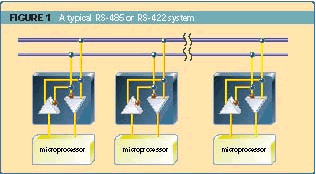
The bus wiring for a typical RS-485 or RS-422 implementation is shown in Figure 1.

Figure 1. Typical RS-485 or RS-422 bus wiring
With this architecture, each station on the network takes turns talking typically by employing some form of token passing scheme, whereby the owner of the token has the right to talk. If the owner of the token doesn’t wish to talk, then it simply passes the token to the next station. In this article I’ll explain why it’s so difficult to ensure that only one processor talks at a time, and I’ll give you a number of possible solutions.
Multidrop transmit enable problem
A typical microcontroller will have some form of UART driver. The transmitter side of the driver’s job is to take characters out of a buffer and feed them to the transmitter of the UART. In its crudest form, this driver is polled, with the code looking something like this:
{
int j;
for (j = 0; j < len; j++)
{
/* Wait for transmitter to empty */
TX_REG = *buf++;
}
}
This approach works fine with point-to-point protocols such as RS-232. However, when we move to multidropped systems, the problem is more complex because we must now also control the transmit enable line. The first time most people come up against this problem, they typically modify the above code to look like this:
{
int j;
TX_ENABLE();
for (j = 0; j < len; j++)
{
while (STATUS_REG & TX_FULL);
TX_REG = *buf++;
}
TX_DISABLE();
}
It doesn’t normally take too much testing before they discover that the last character (or more) isn’t being transmitted. After scrupulously checking the buffer indexing code and so on, the poor software programmer eventually realizes that the transmitter is being turned off too early. That is, the last character is being shifted out of the UART but is never making it past the RS-485 transceiver because by that time the transceiver has been turned off. The reason that this occurs is that the status register on most UARTs tells you when you’re free to write another byte to the transmitter. This isn’t the same as saying that the transmitter has finished shifting out all previous bytes. Even simple UARTs (such as those found on the 8051, 68HC11, and the like) are double buffered, while sophisticated UARTs may have transmitter
FIFOs that can buffer up to 128 bytes. Thus, depending on the size of your transmitter’s FIFO and your communications speed, it may be many milliseconds between writing the last byte to the transmitter and it being safe to disable the transmitter. This gap presents a big problem! Further thought shows that the corollary to this problem is equally bad. That is, failure to turn the transmitter off as soon as the last bit has been transmitted leads to the possibility of line contention. For example, consider the typical token-passing bus system I mentioned in the introduction. The owner of the token has just passed the token to the next station, which has been patiently waiting for its turn to talk. As soon as it receives the token, the recipient may start transmitting (on well-designed, high-performance systems, the delay from token receipt to start of transmission is well under the transmission time for a single character). If the passer of the token has not disabled its transmitter in time, then the network will crash and life will be generally miserable for everyone.
Suggested solutions
Thus, to state the problem succinctly, we need to enable the transmitter just prior to transmission and disable it as soon as possible after the last bit of the last byte has been transmitted. A number of ways of doing this exist, varying from the downright crude to the fairly elegant. Here are your options.
Option 1: Delay loop
The crudest of all possible solutions is the simple software delay loop. A first pass at this code would look like this:
{
int j;
TX_ENABLE();
for (j = 0; j < len; j++)
{
while(STATUS_REG & TX_FULL);
TX_REG = *buf++;
}
delay(TX_FIFO_LEN_PLUS_ONE_CHAR_TIMES);
TX_DISABLE();
}
The concept is simple enough. After putting the last byte into the transmit FIFO, one delays the appropriate amount of time so that the byte has time to be shifted out. Incidentally, don’t assume that this approach is necessarily unacceptably inefficient. If your baud rate is high (say, 500Kbps), then your character time is only 20 microseconds. Twiddling your thumbs for a few tens of microseconds may be perfectly acceptable. Despite the simplicity of the solution, a little thought soon reveals a subtle bug in this approach. This problem is best illustrated with an example.
Consider a double-buffered transmitter (FIFO length = 1). If the above code were required to transmit a buffer of length n, then the following would happen, assuming the transmitter is in an idle condition:
- The first byte would pass straight from the hold register to the shift register
- The second byte would then be immediately written to the hold register
- The third byte would wait for the first byte to be shifted out before being placed in the hold register, and so on until the nth byte was placed in the transmit hold register
- The code would delay two character times (the time to shift out the n – 1 byte in the shift register plus the nth byte in the hold register)
- The transmitter would be turned off
Thus, the code appears to do exactly what we require. However, what happens if we need to transmit just one byte, such as an ACK or a NAK to a previously received command? In this case, the single byte would be passed straight through to the shift register, and we would end up delaying for one character time too long. As I mentioned previously, this is a bad thing because the next person to talk on the link may be already trying to talk, leading to line contention. Thus, if your communications protocol ever calls for the transmission of message blocks shorter than the transmit FIFO length plus one, you’ll need to modify the above code to take this into account.
Option 2: System call
If you’re using an RTOS, it almost certainly provides some sort of wait() or sleep() system call that allows the calling task to be suspended for the specified interval. Thus, the above code might be modified to replace the
with
This approach is acceptable because it dispenses with the inefficiency of the software delay. But you need to be aware of exactly how your RTOS works-particularly with the granularity of timer intervals, whether this task has a high enough priority, and how long the RTOS takes to perform a task switch. Get these wrong, and the time interval you end up waiting could be much longer than you requested, such that line contention again becomes a problem.
Option 3: Hardware timer
If you have a spare timer, kicking off the timer with the appropriate value is a method that avoids both tying up the CPU in a delay loop, and having to rely on the uncertainties of a wait() call. The code would look something like this:
{
int j;
TX_ENABLE();
for (j = 0; j < len; j++)
{
/* Wait for tx fifo to have space */
TX_REG = *buf++;
}
timer_enable(TX_FIFO_LEN_PLUS_ONE_CHAR_TIMES);
}
void timer_enable(uint delay)
{
}
/* Timer ISR */
void timer_interrupt(void)
{
TX_DISABLE();
}
That is, the transmitter is turned off in the timer ISR. This approach works well. Its main drawbacks are the consumption of a timer and the fact that the code for controlling the transmitter is split between two disparate functions, making the code harder to maintain. Again, you have to make sure that you call the timer with the appropriate delay interval when the buffer length is less than the transmit FIFO length plus one.
Option 4: Transmission padding
This method is crude and has flaws, but can work if you’re stuck with a hardware/software architecture that precludes other options. The concept is simple. Take the message to be transmitted and append to it as many pad characters as the depth of your UART’s transmit FIFO plus one. That is, in the case where the transmitter is just double buffered (one byte FIFO), you add two innocuous characters to the end of your message. You can then use the first code example directly. The result looks something like this:
{
char buf[] = { ‘h’,’e’,’l’,’p’,’\0′,’\0′ };
tx(buf, sizeof(buf));
}
void tx(char *buf, int len)
{
int j;
TX_ENABLE();
for (j = 0; j < len; j++)
{
/* Wait for transmitter to empty */
TX_REG = *buf++;
}
TX_DISABLE();
}
In this case, we add two nul characters onto the string “help.” When the “p” of “help” is moved into the transmit shift register, the first nul character is moved by the software into the transmit hold register of the UART. Once the “p” has been shifted out, the first nul character is moved into the shift register, while the second nul character is moved into the hold register. At this point, the for loop will terminate, and we disable the transmitter. It doesn’t take much thought to realize that the start bit and maybe even the first bit of the first nul byte might make it out onto the network before the transmitter is disabled. Whether this matters is system dependent. Note also that if your code is interrupt driven (which is the normal case), the time from the first nul byte being moved into the shift register to the transmitter being disabled will be the worst-case transmit interrupt latency of your system. This latency needs to be much shorter than the transmission bit time for this approach to be effective.
Option 5: “Sophisticated” UART
Most full-featured UARTs, such as the Exar ST16C550, now include a flag in the status register to indicate that the transmit shift register is empty. In this case, our example polled driver code now looks like this:
{
int j;
TX_ENABLE();
for (j = 0; j < len; j++)
{
while(STATUS_REG & TX_FULL);
TX_REG = *buf++;
}
while (STATUS_REG & TX_BUSY);
/* Wait for shift register to empty */
TX_DISABLE();
}
Although this looks like a panacea, you may end up bitterly disappointed with such a UART. A couple of months ago, I was working on a system that used this UART in an RS-485 multidropped system. The 16C550 has nice 16-byte TX and RX FIFOs, and all my messages were less than 16 bytes. Furthermore, the system was to be interrupt driven, as my CPU had a lot to do, and the baud rate was low (9600 baud and fixed by the other equipment). I had given the data sheet a cursory look merely to confirm that the chip did support a flag indicating when the shift register was empty. Thus, I was all set to easily control my RS-485 transmitter, with minimal overhead, when I discovered the gotcha. The 16C550 does not interrupt upon the shift register emptying. Thus, to use the line idle feature, one has to poll-completely defeating the benefit of the transmit FIFO-the transmit interrupts and so on. How this “feature” made it into the marketplace is beyond me. I also suspect that I’m not the first person to point out this shortcoming, since in newer UARTs, such as the XR16C850, the designers have implemented a complete RS-485 mode. In this case, the UART provides a control line that is asserted whenever it’s transmitting data. This control line may be connected to the transmit enable line on the RS-485 transceiver, and the problem is solved.
In my case, however, I was stuck with the 16C550, so I had to fall back on the best software method for controlling the transmitter, namely the loop-back mode.
Option 6: Loop-back
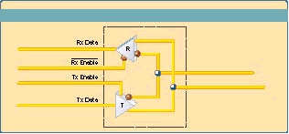
This method is by far the most elegant and robust. It relies on your receiving the data that you transmit and using the received data to decide when to disable transmission. However, to use this approach, your RS-485 transceiver must be wired correctly. The typical RS-485 transceiver is based on the 75176. This chip’s block diagram is shown in Figure 2.

Figure 2. RS-485 transceiver block diagram
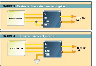
Note that the chip consists of a differential transmitter (“T”) and a differential receiver (“R”), each with its own enable line. The output of the transmitter is internally connected to the input of the receiver (a feature that we will exploit shortly). Careful examination of the enable lines shows that the transmit enable line is active high, while the receive enable is active low. This leads to one of two common hardware configurations. The first (Figure 3) shows the receiver and transmitter enable lines tied together, such that if the receiver is enabled, the transmitter is disabled and vice versa, while the second (Figure 4) shows the receiver permanently enabled.

Unfortunately, the arrangement shown in Figure 3 is the most common. To use the loop-back method, the 75176 must be wired such that its receiver is permanently enabled, as in Figure 4. (An acceptable alternative to the arrangement in Figure 4 is where the receiver enable line is under direct software control.) If you do not have Figure 4’s hardware arrangement, you must resort to one of the methods described earlier.
The loop-back method is at its most robust when all messages over the network start and end with unique characters (although variations on this theme are possible when this isn’t the case). To illustrate the approach, consider a communications protocol that starts all its messages with an STX character, ends them with ETX, and uses only printable characters in between. In this case, we set up the UART driver to be interrupt driven, and in the receiver’s interrupt service routine we unconditionally turn off the transmitter whenever we receive an . The code looks something like this (minus all the buffer handling, interrupt turning on and off, and so on):
{
// If so, force the transmitter on
TX_ENABLE();// Write the byte
TX_REG = tx_buf[op++];
// Rest of code goes here
}
void rx_interrupt()
{
if (res == ETX) // Is it ETX?
TX_DISABLE(); // Force transmitter off//Store byte in buffer etc
}
This approach offers two very clear benefits:
- You are guaranteed not to turn the transmitter off too early (since reception of the terminating character requires that it had been transmitted out of the transceiver)
- The latency from transmitting the last bit to turning off the transmitter is your own receiver interrupt latency, which is normally far less than the time it takes the next station to decide to start talking; thus the probability of line contention is virtually zero
The biggest drawback to this approach is the fact that you’re now burdening yourself with listening to your own transmission. If this condition is unacceptable, the code can be refined such that your UART’s receiver is only enabled immediately prior to transmission of the byte. As an alternative, many microprocessors offer a nine-bit transmission mode, where the ninth bit can be used as a wake up bit. In this case, simply ensure that the and bytes have their wake up bits set.
Final thoughts
The bottom line of the discussion is this: in the unlikely event that your hardware designer asks your opinion on a proposed design, you should beg, plead, and grovel to ensure that the receiver enable line is not disabled when you’re transmitting. If the hardware designer demurs, citing power consumption issues or other real world trivia give that designer a copy of this article and ask him or her to write the driver. Then sit back and wait.
This article was published in the August 1999 issue of Embedded Systems Programming. If you wish to cite the article in your own work, you may find the following MLA-style information helpful:
Jones, Nigel. “Controlling the Transmit Enable line on RS-485 Transceivers” Embedded Systems Programming, August 1999.